Oil & gas, petrochemicals, power generation, and water treatment plants are complex industries that have to deal with high-stakes environments on an everyday basis. Even a small oversight can lead to costly errors or serious safety risks. That’s why having clear, accurate plant design and drafting diagrams isn’t just beneficial – it’s important.
For this, engineers rely on two key tools throughout a plant’s lifecycle: the Process Flow Diagram (PFD) and the Piping and Instrumentation Diagram (P&ID) that help communicate process details clearly at every stage.
While PFDs and P&IDs might look similar to the untrained eye, they actually serve very different purposes. Knowing the difference – and how both are used together – can help piping design and drafting engineers avoid miscommunication, delays, and expensive mistakes.
What is a Process Flow Diagram (PFD)?
Think of a Process Flow Diagram as the big-picture map of your system. It shows how the process works by outlining the flow of materials, major equipment (like reactors, distillation columns, or compressors), and the main pipelines connecting them.
But here’s the catch – PFDs don’t get into the details.
They leave out smaller components like valves, instrumentation, or control loops. Instead, they focus on:
- Overall flow direction
- Key equipment involved
- Basic process conditions (e.g., temperature and pressure)
- Main process streams with flow rates
Process flow diagrams are typically used in the early stages of a project when teams are trying to understand the scope of the process and make high-level decisions. They are especially useful for feasibility studies, cost estimation, and initial plant layout planning.
Source: Processdesign
The primary objective of these plant design and drafting diagrams is to:
- Provide an overview of the entire process system
- Depict how materials and energy move through major components
- Serve as the starting point for process simulation and design
- Assist with mass and energy balance calculations
Key Elements in a PFD:
- Major Equipment, like reactors, pumps, compressors, heat exchangers, separators, distillation columns, etc.
- Process Streams – lines – showing the flow of materials (gas, liquids, vapors) with arrows indicating direction.
- Operating Data (typical values) for pressure, temperature, flow rate, and compositions.
- Material Balance Information
- Simple control structures showing level or flow controllers
PFDs are commonly created during the conceptual or preliminary plant design phase. They are useful for project engineers, simulation analysts, consultants, and decision-makers who need a bird’s-eye view of plant operations.
However, they do not provide detailed information about instrumentation, control systems, or how each piece of equipment connects through valves, sensors, and lines. For this, Piping and Instrumentation Diagrams (P&IDs) are required.
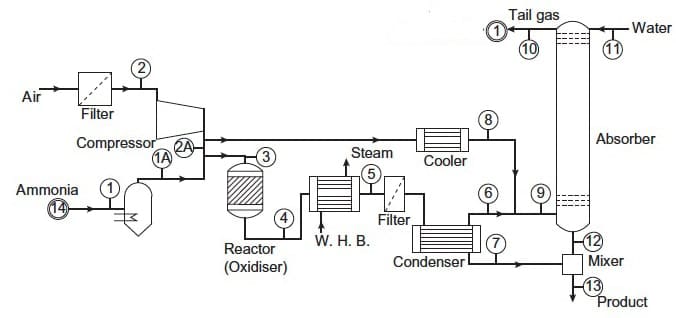
What is a Piping and Instrumentation Diagram (P&ID)?
A Piping and Instrumentation Diagram (P&ID) offers a detailed representation of the physical arrangement and interconnection of piping, equipment, instruments, and control systems within a process plant.
In fact, it won’t be wrong to say that where the PFD stops, the P&ID begins. A P&ID breaks down the process into actionable engineering details, showing how everything is connected and controlled.
Source: Research Gate
The primary objective of a P&ID drawing in plant design engineering services is to:
- Guide the detailed design, construction, and layout of process systems
- Provide accurate and traceable system documentation
- Serve as a basis for operations, instrumentation, and maintenance
- Support safety and compliance audits, like HAZOP studies
Key Elements in a P&ID:
- Detailed shapes, tags, and specifications for each piece of equipment.
- Exact size, material specs, number, and routing detail of the piping system.
- Exact details of valves and fittings
- Complete instrumentation detail
- Details of the safety systems – relief valves, rupture discs, alarms, and emergency shutdown systems
In fact, P&ID contains every minute detail that’s essential to physically construct, safely operate, and maintain a system over time.
|Also Read: Key Challenges While Creating Piping and Instrumentation Diagram (P&ID) & How to Solve Them|
Why Both Diagrams Matter
A successful plant design doesn’t rely on just one of these documents. PFDs and P&IDs work hand-in-hand to transition a concept into a working facility.
- PFDs help everyone – from designers to investors – understand what the system is supposed to do.
- Piping and instrumentation diagrams, on the other hand, show exactly how to build and control that system.
Using both during plant design and drafting ensures:
- Efficient design communication
- Fewer errors in procurement and construction
- Better operational training
- Safer system startup and maintenance
Final Thoughts
Understanding the difference between PFDs and P&IDs is important for anyone involved in process design or plant operations. While they may appear similar, each serves a specific role in the project lifecycle and ensures engineering accuracy, operational safety, and regulatory compliance.
Whether you’re designing a new plant or upgrading an existing one, always ensure your documentation strategy includes both high-level process flow (PFD) and detailed system control (P&ID) diagrams.
If you need help developing accurate and standards-compliant PFDs or P&IDs, we are here to help. At Enginerio, we specialize in providing detailed, ISO and ANSI-compliant plant engineering services tailored for Oil & Gas, Chemical, Water Treatment, and other sectors. Contact us today for expert plant design and drafting, and process documentation support.