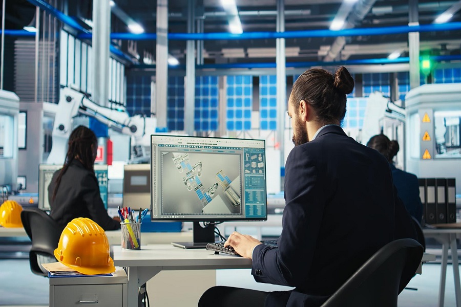
Sheet metal fabrication is an extremely important part of product design and development. It impacts everything from cost and efficiency to durability and assembly. Whether you’re designing enclosures, brackets, or complex assemblies, using the right tools and following best practices to improve efficiency, reduce rework, and speed up production.
SolidWorks and AutoCAD are the two software widely used in sheet metal design services. While SolidWorks comes with dedicated sheet metal tools for unfolding and bend allowance, which makes it ideal for 3D sheet metal design and manufacturing integration, AutoCAD provides flexibility for 2D layouts and precise detailing and is useful for creating flat patterns and drafting complex geometries.
|Also Read: AutoCAD vs. SolidWorks: Choosing the Right Software for Sheet Metal Projects|
However, regardless of the software you choose, it is important to follow industry best practices to avoid common pitfalls (such as incorrect bend allowances, weak joints, and material waste) during sheet metal designing.
This guide covers essential best practices that every designer should follow to create efficient, production-ready sheet metal drawings while maximizing the potential of AutoCAD and SolidWorks.
Key Guidelines Every Designer Must Follow When Working with Sheet Metal Models
1. Use Feature-Based Parametric Modeling (FBPM)
Feature-based parametric modeling is a design approach that allows designers to create 3D sheet metal drawings using predefined features and parameters like dimensions, constraints, formulas, material properties, and more. It establishes relationships and constraints between different elements of a model and ensures that the design remains adaptable and easily modifiable – without needing to recreate components from scratch.
Most designers rely on SolidWorks parametric modeling. SolidWorks excels in FBPM and allows users to create intelligent, rule-based models that automatically adjust to design changes.
Benefits of FBPM:
- It enables quick part modifications using 3D parametric designs and offers increased opportunities for design automation and rule-based modeling
- FBPM ensures better alignment of features with shape, geometry, and dimensions
- FBPM reduces 70-90% of the time spent in creating 2D detailed drawings
- It enhances communication across teams and improves the quality of design and manufacturing documentation
2. Follow Top-Down Design Approach
Implement a top-down approach to model multi-component sheet metal assemblies. This method allows designers to create a master model that defines the overall geometric framework and makes sure that all space constraints are properly assigned to all components and sub-assemblies.
Top-down approach is particularly useful for Configure-to-Order (CTO) and Engineer-to-Order (ETO) product customization, such as doors, windows, and furniture.
Advanced CAD tools like SolidWorks, Inventor, and Creo efficiently support this approach, making it suitable for both large-scale industrial systems with thousands of components and smaller assemblies, such as sheet metal door frames with 20-30 parts.
Benefits of Top-Down Design Approach:
- Supports parametric customization of multiple components
- Enhances large-scale design automation
- Simplifies constraint management and individual part development
- Facilitates quick assessment of dimensional changes and their impact on assemblies
- Ensures alignment with functional, spatial, and aesthetic design requirements
3. Adhere to DFM/DFMA Guidelines
Design for Manufacturing (DFM) and Design for Manufacturing and Assembly (DFMA) help engineers align designs with real-world fabrication capabilities. By following these guidelines, designers can prevent common errors related to manufacturing constraints and ensure optimal efficiency.
DFM principles bridge the gap between theoretical design and practical implementation, especially for features like holes, slots, bends, and reliefs. DFMA further streamlines production. It reduces the number of components and simplifies the assembly process, leading to cost savings and faster production cycles.
Advantages of DFM and DFMA:
- Reduces design revisions caused by shop floor inconsistencies
- Ensures parts meet both assembly and manufacturing requirements
- Optimizes assembly by minimizing component count
- Leads to 70-80% reduction in costs
- Increases manufacturing speed by over 30%
- Eliminates rework through strict adherence to DFM principles
4. Stick to Model-Based Definition (MBD) Approach
Advancements in CAD tools like SolidWorks now allow for the inclusion of extensive manufacturing and quality information within models. With MBD, product manufacturing information (PMI) can be embedded into the model, which helps in the creation of a single source of truth for all stakeholders.
MBD streamlines the design-to-manufacturing workflow. It reduces dependency on 2D drawings and improves efficiency across teams. When combined with DFM, DFMA, FBPM, and the top-down approach, MBD offers manufacturers a powerful tool to enhance collaboration and precision.
Advantages of MBD:
- It makes way for centralized data management – for manufacturing, quality control, and suppliers
- MBD eliminates the need for 2D drawings in component manufacturing
- It accelerates design-to-manufacturing speed by over 80% and provides clear and effective communication with stakeholders
- MBD improves coordination, reduces errors in communication, and ensures smooth part manufacturing
5. Validate Designs with Simulation Tools
Integrate simulation tools into your design process to predict real-world performance of your product (and identify potential failures) before manufacturing begins. Advanced CAD software like SolidWorks, Autodesk Inventor, and CATIA offer built-in Finite Element Analysis (FEA) and stress-testing capabilities. You can use them to simulate your model, detect weak points in sheet metal parts, if any, and study the thermal behavior of your product under various loads.
Advantages of Using Simulation Tools:
- Simulation tools help you to refine geometries and optimize material usage without the need for costly prototyping.
- It ensures parts can withstand expected mechanical, thermal, or vibrational stresses
- Streamlines the design validation process, allowing faster approvals and production
- Reduces rework and material waste by fine-tuning thickness and reinforcement areas
- Incorporating simulation-driven design validation ensures that sheet metal components meet both structural and functional requirements while reducing risks, costs, and manufacturing errors
Save Cost and Reduce Rework Using Sheet Metal Fabrication Drawing and Modeling
Mastering sheet metal modeling isn’t just about design – it’s about making fabrication faster, smarter, and more cost-effective. By using the right sheet metal modeling techniques and practices, manufacturers can reduce waste, speed up production, and ensure precision. With up to 90% less rework and major cost savings, these methods can help you stay competitive in today’s market.
Want to embrace the best practices in sheet metal modeling? Partner with Enginerio and deliver high-quality, optimized products while keeping fabrication costs in check. Our CAD designers follow the best sheet metal modeling practices to deliver high-quality, optimized products while keeping fabrication costs in check.
Contact us today to know more about our services and solutions or to request a customized quote.