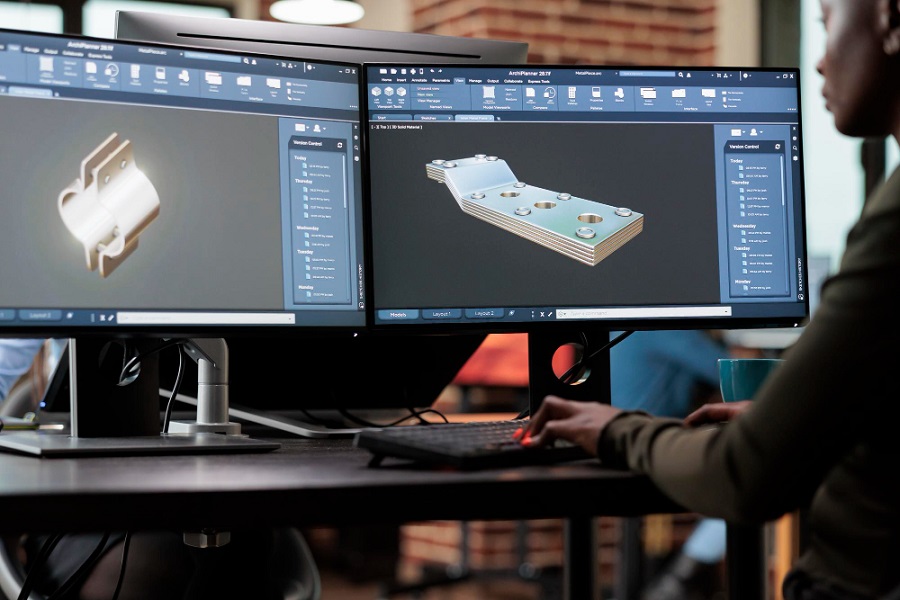
When it comes to modeling sheet metal parts and assemblies, SolidWorks always remains the top choice. A powerful 3D modeling tool, SolidWorks simplifies the design process and helps designers break down assemblies into part drawings. With its 3D capabilities, it optimizes the entire design process and helps in the creation of production-ready designs quickly and easily.
The software offers a host of features that can improve your design and manufacturing processes. Whether you are creating individual components or complex sheet metal structures, SolidWorks provides a host of tools, commands and shortcut options to expedite the process. Some of the key advantages of SolidWorks sheet metal drawing include:
- Creation of realistic 3D renderings and animations of your sheet metal designs for presentations, design reviews, and marketing materials.
- Flexibility and precision in sheet metal designs enable the creation of accurate models that align with your design vision.
- User-friendly interface and diverse array of tools and commands that simplify the creation of complex sheet metal geometries, flanges, hems, and more.
- Automatic calculation of bend allowances based on material properties and thickness, eliminating the need for manual calculations.
- Parametric modeling capabilities that enable designers to make changes to the original design and automatically update it across the entire model.
- Integrated simulation tools for stress analysis, thermal studies, and motion simulations. This ensures that your sheet metal components meet performance and safety requirements.
- Access to a comprehensive library of standard sheet metal components and fasteners for efficient modeling.
- Smooth integration with other manufacturing software, such as CNC programming tools, for a streamlined design-to-fabrication process.
Tips for Efficient SolidWorks Sheet Metal Modeling
Though SolidWorks has many capabilities, following a handful of practices can make the sheet metal modeling process a whole lot easier. Here are the top six tips that every SolidWorks user needs to know:
1. Use SolidWorks Sheet Metal Module
For efficient SolidWorks 3D modeling, start with its specialized sheet metal module. Thus, when designing metal components from thin plates or sheets, designate them as sheet metal parts. SolidWorks will then initiate the dedicated sheet metal module and introduce the appropriate properties. This automatic addition of sheet metal instructions streamlines your product design, helping maintain precision and manufacturability.
2. Leverage the Prowess of Weldments Module
Always design your fabrication assemblies of parts using SolidWorks weldments module. Especially, if the assembly requires welding of structural parts. Using this module, you can create 2D or 3D structures in just few clicks. Multiple weldment profiles can be created as library features; even different configurations of a structural member can be saved in one profile. The final model can then be created by optimizing the pre-loaded shapes. This helps to save a lot of time and effort. The biggest benefit of the weldments module is that it creates two configurations by default, one for the machined parts and the other for the 3D solid welding parts.
3. Harness SolidWorks Flexibility for Complex Sheet Metal Shapes
While the sheet metal module is the preferred starting point, you may sometimes need to begin with free-form 3D solid models. These models can later be converted to sheet metal models using SolidWorks’ shell function. This approach is particularly useful for designs for special purpose machines (SPMs) or HVAC ducts. It simplifies the modeling process and reduces the number of required steps.
4. Develop Sheet Metal Parts with Constant Sheet Thickness and K Factor
Sheet metal parts are fabricated from various metals, including steel, aluminum, bronze, copper, etc., with specific thickness requirements. The springback factor or “K” factor is needed to develop precise bends and accurate flat patterns on sheet metal parts. SolidWorks sheet metal modeling empowers users to choose the material type, its thickness, and other parameters for creating sheet metal parts.
The Bend Table feature in SolidWorks animation empowers users to precisely define and tailor the bend allowance and deduction values according to specific thickness and material. By doing so, this tool plays a crucial role in ensuring that the right material is utilized for each bend in the design. This not only prevents material wastage but also contributes to cost reduction, making the manufacturing process more efficient and sustainable. With the ability to fine-tune these parameters, SolidWorks users can optimize their sheet metal designs for maximum accuracy and minimal resource utilization.
5. Employ SolidWorks Top-Down Approach for Assembly Creation
Parametric modeling in SolidWorks streamlines the design process for bulky sheet metal assemblies, saving time during design modifications. Designers must use SolidWorks top-down approach to efficiently create and modify sheet metal assemblies. This makes addressing the needs and demands of sheet metal fabricators quite easier.
Top-down assembly modeling in SolidWorks refers to the process of creating an assembly by establishing a relationship between components at the assembly level before generating individual parts. It helps to streamline the sheet metal assembly designs by defining the overall structure, constraints, and interactions between components within the assembly.
6. Prioritize Center and Symmetry
For precision and ease of manufacturing, it’s crucial to make the coordinate systems in your CAD software match those of CNC machines. Utilize symmetry in your sheet metal modeling to save manufacturing time. it also facilitates quick adjustments like cutter positioning and sheet nesting. Techniques such as mirroring and mating during 3D modeling can further enhance symmetry, resulting in less rework and a smoother design process.
Conclusion
While 3D modeling tools give sheet metal fabricators an edge over others, SolidWorks parametric modeling takes 3D designing to an altogether new level. It offers sheet metal modelers countless ways to enhance their efficiency.
Need help with SolidWorks Design and Modeling? Hire our SolidWorks experts and transform your design concepts into precise and realistic 3D models. At Enginerio, we offer specialized SolidWorks Design and Modeling Services to help you transform your handmade mockups and CAD drawings into precise 3D SolidWorks CAD models.
Connect with us to leverage the advanced features and capabilities of the SolidWorks software and take your designs and ideas to the next level!


