In Process-based Industries like Oil & Gas, Chemical Processing, Water Treatment, and Power Plants, it is extremely important to know how systems are built and how they function. Piping and Instrumentation Diagram (P&ID) services help professionals visualize and manage these complex systems like a pro!
A P&ID is a detailed diagram that shows the piping, equipment, valves, instruments, and control systems within a process plant. Think of it as a blueprint or a visual depiction that engineers, technicians, and operators can use to understand how everything is connected and how the process flows.
It includes the following information:
- The equipment used in the plant – pumps, tanks, heat exchangers, etc.
- The arrangements of pipes and how they are connected
- Placement of valves and instrumentation
- Details about the control and safety systems
Why Are P&IDs Important?
A P&ID helps engineers and operators comprehend the design and functionality of the system.
- Engineers use them to plan the system layout
- Operators refer to them to run and maintain systems efficiently
- P&IDs show critical safety features and help meet regulatory standards
- Technicians rely on them to diagnose and fix process issues.
How is a P&ID Created?
Creating a P&ID involves several structured steps:
1. Collecting Process Information
The first step in creating a Piping and Instrumentation Diagram involves gathering all necessary process details. Engineers carefully review the Process Flow Diagrams (PFDs) to understand the overall flow of the system. They also collect detailed equipment specifications like pump capacities, vessel sizes, construction materials, and any specific process requirements from the respective manufacturer manuals and technical documentation. Additionally, client standards and project-specific guidelines are thoroughly reviewed to ensure the final diagram aligns with expectations and industry regulations.
2. Choosing Design Standards
Once all process information is collected, appropriate industry standards are selected to maintain consistency and clarity. Commonly followed standards include:
- ISA S5.1: For instrument and control device symbols
- ISO 10628: For process diagrams in the chemical and petrochemical industries
Adhering to these standards is important as it ensures that the P&ID is universally understood and easily interpreted by professionals across different teams and locations.
3. Drafting Equipment Layout
The layout of all major equipment is then drafted. This includes pumps, tanks, heat exchangers, reactors, and vessels. A unique tag or identifier is added to each piece of equipment to clearly label it. For example, P-101 for Pump 101 or T-102 for Tank 102. This makes the diagram easy to navigate.
4. Adding Piping & Flow Directions
The next step is connecting them with the appropriate piping systems. P&ID experts draw the pipelines to provide accurate connections between equipment. The size, material, and flow direction arrows of pipes are marked to show how fluids, gases, or slurries move through the system. These elements are vital for process efficiency and safety.
5. Placing Valves and Fittings
Once the piping system is in place, valves and fittings are added at specific locations along the pipelines. Depending on the requirement, different types of valves, like manual valves, check valves, and control valves, are added to regulate flow, pressure, or direction. Elbows, tees, reducers, and flanges are also included for optimum system operability.
6. Incorporating Instrumentation and Control Lines
The next step is the integration of instrumentation devices into the diagram. Instruments like pressure gauges, temperature sensors, flow meters, and control panels are inserted using standardized symbols. Dash and dotted lines are drawn to represent communication between instruments and control systems like PLCs or DCS units. This layer helps operators monitor and control the process efficiently.
7. Review and Final Approval
Before the P&ID is finalized, it undergoes a meticulous review process. Engineers and stakeholders perform detailed checks to verify accuracy and compliance with safety standards. Once the drawings are approved, the P&IDs are finalized and they become an essential reference tool for the plant’s lifecycle, right from design to construction to operations and maintenance.
Common Piping and Instrumentation Diagram Symbols
One of the most important aspects of reading a P&ID is understanding the symbols. Here’s a handy table of commonly used P&ID symbols:
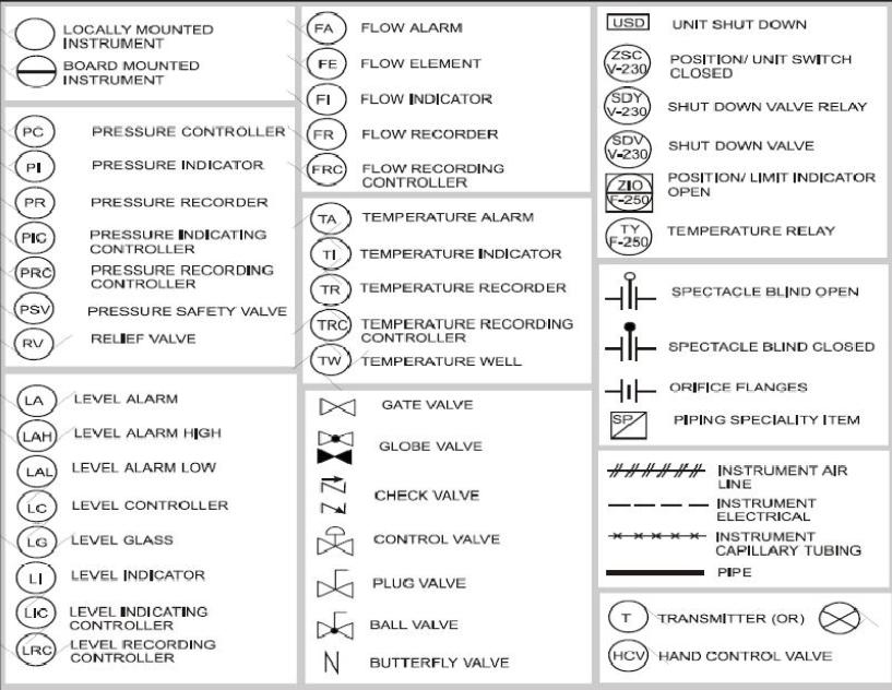
[Image Source: instrumentationtoolbox]
How to Read a P&ID?
Once you get familiar with the symbols, reading a P&ID becomes easier. Here’s a step-by-step approach:
1. Start with the Legend
Check the diagram’s legend – it describes all symbols and abbreviations used.
2. Identify Major Equipment
Look for large components like tanks, pumps, and heat exchangers. They’re typically labeled:
- T-101 = Tank 101
- P-102 = Pump 102
3. Follow the Piping Lines
Solid lines represent pipes. Follow them to see how fluids or gases flow between equipment. Keep an eye on:
- Pipe size and material tags
- Flow direction arrows
4. Locate Valves and Fittings
Valves control the flow, whether it’s manual or automatic. Check valve types and positions:
- Gate Valve: Basic open/close control
- Control Valve: Adjusts flow rate, usually connected to instruments
5. Understand Instrumentation
Look for circles with codes like:
- PT-101: Pressure Transmitter
- FT-202: Flow Transmitter
- TT-303: Temperature Transmitter
Dashed lines will show how instruments connect to control panels or systems.
6. Check Control Loops
A control loop shows how sensors, controllers, and actuators interact to keep the system balanced. It helps operators monitor and adjust the process in real-time.
Final Thoughts
A Piping and Instrumentation Diagram may seem complicated at first, but it is a visual map of your process system and plays a key role in the design, safety, maintenance, and troubleshooting of your plant. By understanding the symbols and flow logic, you can easily navigate any P&ID with confidence.
Need Accurate, Compliant P&IDs?
Our P&ID experts can help you develop clear, precise, and industry-compliant diagrams tailored to your needs. Our expertise includes:
- Detailed P&ID creation
- Point cloud to CAD conversions
- 3D modeling for piping arrangements
- Construction documentation for piping systems
- Pipe stress and flexibility analysis
- Compliance assurance with global standards
Contact us today to ensure your process systems are designed accurately right from the start!