
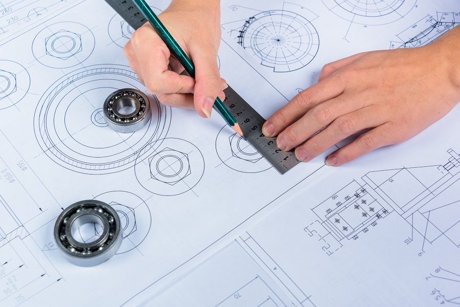
A fabrication drawing is a trade-level document used to convert a design into something that can be manufactured accurately. It typically includes dimensions, materials, tolerances, weld details, connection information, and notes that remove ambiguity from the shop floor.
In mechanical, structural, and MEP projects, clear drawing documentation is what turns design intent into buildable work. A well-prepared fabrication engineering drawing gives the shop the information needed to cut, form, weld, assemble, inspect, and install components with confidence.
These documents are often called fabrication shop drawings, workshop drawings, or production details depending on the discipline and stage of the project. In practice, they sit between design intent and shop execution, which is why they matter so much in engineering and manufacturing workflows.
This article explains what fabrication is in mechanical engineering, what a GA drawing is and how it differs from a fabrication detail, the main types of drawing in mechanical engineering, how fabrication/manufacturing drawing and detailing supports real production, and where fabrication shop drawing services add value in steel, MEP, ducting, pipework, and mechanical projects.
What is a Fabrication Drawing?
A fabrication drawing is a detailed engineering document used to manufacture a component or assembly. It translates design intent into exact instructions for the workshop, including sizes, materials, joints, tolerances, and assembly references.
What Is Fabrication in Mechanical Engineering?
Fabrication in mechanical engineering is the process of making components or assemblies from raw materials using cutting, bending, welding, machining, fastening, or assembly operations. It is the point where a concept becomes a physical part that can be tested, installed, or commissioned.
Workshop Drawings and Trade Detailing
Workshop drawings are the backbone of trade-level detailing. They tell the fabricator exactly how a part, subassembly, or system should be made.
A good workshop drawing should answer practical shop questions:
- What material is required.
- What dimensions matter.
- Which tolerances apply.
- Where welds, holes, bends, or cutouts go.
- How parts fit together.
- What the final orientation should be.
This is why workshop drawings are often the deliverable that bridges engineering, procurement, and production.
Fabrication Drawings vs Shop Drawings vs GA Drawings
These terms overlap, but they are not always the same.
| Drawing type | Main purpose | Typical use | Level of detail |
| GA drawing | Shows overall arrangement and coordination | Space planning, interfaces, layout review | Medium |
| Shop drawing | Supports approval and coordination | Client/consultant review, installation planning | High |
| Fabrication drawing | Gives shop-ready build instructions | Cutting, welding, forming, assembly | Very high |
A GA drawing in mechanical engineering gives the overall picture. A fabrication detail drawing goes deeper and tells the shop how to build the item. In many projects, both are needed, along with supporting schedules and specifications.
What does a Professional Drawing Package Include?
A complete drawing package should support both design review and shop execution. It should include overall and part dimensions, material grade and thickness, weld symbols and joint details, hole sizes and locations, bend lines and angles, orientation marks, assembly relationships, surface finish notes, revision control, and part numbers or BOM references where needed.
Why does this matter?
If information is missing, the shop may stop work, raise an RFI, or make assumptions. That affects cost, schedule, and quality. Good documentation reduces those risks.
Types of Drawing in Mechanical Engineering
There are several common drawing types used in fabrication-heavy projects.
- A fabrication assembly drawing shows how multiple parts fit into one assembly. It is useful for sequencing, fit-up, and understanding part relationships before production starts.
- A fabrication engineering drawing is the more technical, production-oriented drawing used to guide the actual build. It typically contains the exact information the shop needs to manufacture the item.
- Mechanical fabrication drawings are used for frames, machine parts, brackets, supports, housings, skids, and equipment assemblies. It may include machining notes, fits, and connection details.
- Structural fabrication drawings are used for beams, columns, platforms, base plates, braces, handrails, and connection plates. They are common in steel structure work and usually include member marks, bolt patterns, and erection references.
- MEP fabrication drawings support mechanical, electrical, and plumbing coordination. In practice, they often focus on constructability and installation-ready information for coordinated systems.
- Duct fabrication drawings show duct sizes, offsets, seams, joints, gauges, fittings, and connection details. They are common in HVAC and ventilation projects.
- Pipe fabrication drawings support spools, tie-ins, supports, fittings, line numbers, welds, and routing. They are widely used in process plants, utilities, and industrial systems.
Fabrication for Steel Structure
A fabrication drawing for steel structure needs to be clear enough for cutting, drilling, welding, and erection. It should show member sizes, connection details, weld information, hole patterns, base plates, stiffeners, and any field-assembly references.
For steel projects, coordination is critical because fabrication errors often create installation problems later. That is why structural detailing usually requires close alignment between the GA drawing, connection design, and the final workshop output.
How is Drawing Information Extracted?
Teams must know how to read engineering drawings and related specifications correctly. Key points include first-angle and third-angle projection, imperial and metric units, workpiece reference points, datums, tolerancing, title blocks, revision notes, and symbols or abbreviations aligned with relevant BS or ISO standards. Without this, even a well-drawn sheet can be misread.
How Is Fabrication Documentation Produced?
The workflow usually starts with design intent and ends with a shop-ready issue. Teams review requirements, build or reference the model, extract components and interfaces, add dimensions and tolerances, check constructability, verify symbols and conventions, review standards, and issue the final set for approval or fabrication. This reduces revisions, clashes, and communication gaps.
Engineering Drawings for Manufacturing
Engineering drawings for manufacturing must do more than show geometry. They must support a production decision.
A strong manufacturing drawing helps the shop understand:
- What to make
- What material to use
- How to make it
- What tolerance is acceptable
- How the final part should be checked
That is why a clean, readable format is often more valuable than a visually complicated sheet.
Applications by Discipline
Different project types use different detailing priorities.
Structural fabrication drawings
Used in steel buildings, platforms, staircases, frames, and industrial support systems.
Pipe fabrication drawings
Used in process plants, utilities, skids, and modular assemblies.
Duct fabrication drawings
Used in HVAC, clean air, smoke control, and ventilation systems.
MEP fabrication drawings
Used in coordinated building services projects where routing, space, and installation sequence matter.
Mechanical fabrication drawings
Used in machinery, enclosures, skids, fabricated equipment, and custom assemblies.
When do Professional Fabrication Shop Drawing Services Help?
What are professional fabrication drawing services? They are outsourced or specialist detailing services that prepare shop-ready documentation for fabrication, coordination, and approval.
These services are especially useful when:
- In-house drafting capacity is limited.
- The project needs a faster turnaround.
- The scope includes multiple disciplines.
- Shop-level detail must be highly accurate.
- The team needs BIM, CAD, or coordinated fabrication output.
In many projects, fabrication shop drawing services help reduce internal workload while improving drawing consistency and delivery speed.
Autocad and CAD-Based Deliverables
Many teams still expect AutoCAD fabrication drawings because CAD remains a standard delivery format for fabrication and detailing work. Even when projects are modeled in 3D, the final output often includes 2D sheets, schedules, and annotated details that the workshop can use directly.
The key is not the software name itself. The key is whether the output is clear, accurate, and suitable for fabrication.
Industry Example
A fabrication team receives a steel support frame package for a mechanical skid. The GA drawing shows overall arrangement and interfaces. The assembly drawings show how the frame members fit together. The shop drawing package includes material specs, weld symbols, bolt hole locations, and part marks.
The result is a coordinated package that lets the shop cut, weld, assemble, and inspect the frame without guesswork.
Best Practices
- Use clear reference points and consistent units.
- Separate coordination information from fabrication instructions.
- Keep notes short and unambiguous.
- Use the right projection and tolerancing conventions.
- Confirm revision control before release.
- Check every sheet from the shop’s perspective.
- Match the drawing type to the project stage.
Common Mistakes
- Mixing GA information with production detail.
- Leaving out tolerances on critical features.
- Using unclear symbols or inconsistent terminology.
- Overcrowding the sheet with unnecessary notes.
- Issuing outdated revisions.
- Repeating information across too many views.
Relevant Standards
Project standards vary by discipline, but the most relevant references often include:
- ISO for drawing conventions and technical documentation.
- BS standards where UK-style drafting conventions apply.
- ANSI and ASME for mechanical and engineering documentation.
- AISC for steel detailing contexts.
- AWS for welding symbols and weld-related detailing.
Use only the standards that match the actual scope of the project. The goal is clarity and compliance, not citation overload.
Final Thoughts
Good detailing makes fabrication predictable. Whether the project involves steel, ducting, piping, or mechanical assemblies, the drawing package must give the shop enough information to build the first time accurately.
Once fabrication and installation are complete, as-built drawings can be prepared to reflect the final field-installed condition, including any changes made during execution. Enginerio also supports reverse engineering for existing products, helping teams analyze, recreate, and improve parts when original design data is incomplete.
That is why strong fabrication shop drawings, clear workshop drawings, and disciplined revision control are so important. They improve build quality, reduce rework, and support better project delivery from design to installation.