Client Overview
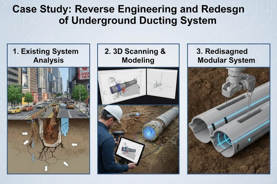
An Australian engineering company approached our team to support the redesign and upgrade of an underground ducting system for an existing plant. The existing ducting infrastructure was outdated, corroded, and required replacement with modern, durable materials.
Project Scope
The project involved:
- Replacing the old underground ducting system with new stainless steel (SS) and later FRP (Fiber Reinforced Plastic) ducts.
- Utilizing 3D scanning data of the existing plant for reverse engineering.
- Developing a detailed SolidWorks model, General Arrangement (GA) drawings, and shop drawings for fabrication and site installation.
- Implementing client-requested design modifications based on site feedback.
Process and Methodology
1. Data Acquisition and Analysis
- Received 3D laser scan data and existing plant layout drawings from the client.
- Imported the scan data into SolidWorks to visualize the actual site conditions and identify discrepancies in the old drawings.
2. 3D Modeling and Design
- Created a 3D model of the existing ducting system using the scan data as a reference.
- Designed the new stainless steel ducting with appropriate flanges, reducers, T-joints, valves, and attachments.
- Generated GA drawings for client review and approval.
3. Client Review and Site Verification
- The client used the GA drawings for on-site verification of the existing layout.
- During the site inspection, the client suggested modifications:
- Replace stainless steel with FRP and other non-corrosive materials for improved durability.
- Reroute specific sections of the ducting and venting systems to improve accessibility and flow.
4. Design Update and Finalization
- Incorporated all client feedback and rerouting requirements.
- Updated the SolidWorks model, GA, and shop drawings to reflect the new FRP ducting system.
- Ensured compatibility of all components, supports, and connections in the revised model.
Challenges
- Managing large 3D scan datasets while maintaining model accuracy.
- Ensuring dimensional accuracy between the scanned environment and the new model.
- Coordinating multiple design changes during the review stage while adhering to project timelines.
Outcome
- Delivered a complete set of updated 3D models, GA drawings, and fabrication-ready shop drawings.
- Achieved full compliance with the client’s updated material and layout specifications.
- The entire reverse engineering, redesign, and drawing production process was successfully completed within 2 months.
Key Tools and Technologies
- SolidWorks (3D modeling, assembly design, drawing creation)
- 3D Scanning Data Integration
- Engineering Standards for FRP Ducting Systems
Value Delivered
- Provided the client with a fully engineered, accurate, and installation-ready design package.
- Improved system durability and performance through the use of non-corrosive materials.
- Enabled efficient on-site installation by minimizing rework through precise modeling.