Project Overview
• Client: Confidential Chemical Plant
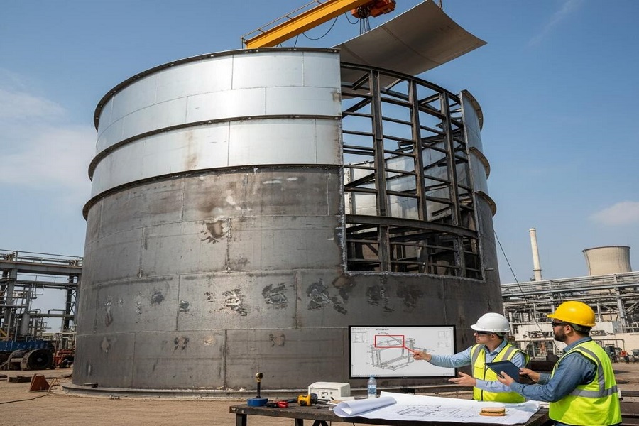
• Project: Design and fabrication support for structural components and flashing on a 5-ton capacity chemical tank
• Software Used: SolidWorks (Weldments & Sheet Metal modules)
• Scope:
1. Design of beams and flashing around the tank
2. Surline panel and Z-flashing for the outer circumference
3. Creation of shop drawings, flattened views, and DXF files for fabrication
Initial Approach
- The project was initiated using SolidWorks Weldments to model beams and Z-flashing components.
- All components, including the outer circumference Z-flashing, were created as part of a single Weldment model.
- The approach was discussed and confirmed by the client before proceeding.
- The team communicated that generating shop drawings, flatten views, and DXF files from a weldment model would be difficult, but due to the urgency of the project, the team proceeded with the weldment-based approach.
Advantages in Early Stages
- Using a single weldment model made the assembly and cutout process straightforward.
- The initial design phase progressed smoothly and efficiently, leveraging weldment features for structural alignment and cut-list generation.
Client Instruction Change & Challenges
- After initial modeling was completed, the client revised the requirement:
o All Z-flashing components had to be converted into individual sheet metal parts.
o The maximum length of each sheet metal part was limited to 4 meters. - This change led to multiple challenges:
o Recreating the Z-flashing components in sheet metal format
o Reassembling them onto the tank model
o Performing assembly cutouts again in the updated model
o Generating accurate flattened views and DXF files became difficult due to cutouts applied at the assembly level
o Regeneration issues arose with flattened views in SolidWorks due to assembly-level modifications
Technical Constraints Identified
- Weldment vs Sheet Metal:
o Weldment parts are optimized for structural components and beam management
o Sheet metal parts are required for flattening and DXF export, but are more sensitive to assembly-level modifications - Flattening Issues:
o Assembly cutouts are not inherently recognized in flattened views
o Flatten feature failures required manual workarounds or part redesigns
Impact & Resolution
- Due to the required shift from weldments to sheet metal:
o The team had to recreate the entire Z-flashing around the tank circumference
o Additional time required: 3 to 4 working days
o Fabrication documentation (shop drawings, DXF files) had to be regenerated from scratch
Key Lessons Learned
1. Define Model Strategy Upfront: Establish whether components should be modeled as weldments or sheet metal from the start based on the final deliverables (e.g., DXF, flattened views)
2. Communicate Constraints Early: In future projects, communicate the limitations and downstream effects of using weldments vs sheet metal early in the design phase
3. Client Sign-Off on Modeling Strategy: Get formal approval on modeling techniques (especially in SolidWorks) before detailed work begins
4. Account for Design Changes in Timelines: Include buffer time in project plans to accommodate potential late-stage client revisions
Conclusion
While the initial approach allowed for rapid modeling using weldments, a late-stage client requirement change necessitated a full rework using sheet metal techniques. Despite tight deadlines, the team was able to adapt and deliver the required documentation, although with an additional effort of 3–4 days. This project highlighted the importance of upfront technical alignment and client communication in CAD-based fabrication projects.