Key Takeaway
The biggest improvement was not simply changing from AutoCAD to SolidWorks. It was changing from a geometry-creation approach to a design-intent and validation-driven engineering approach.
This experience reinforced Enginerio’s philosophy:
Design it right. Validate it early. Build quality into the process.
The project also demonstrated how the right combination of CAD methodology, engineering expertise, assembly validation, and QC can significantly improve the reliability and production readiness of a design.
Client Background
Our client was involved in the design and production of acrylic display stands for cosmetic products. The stands consisted of multiple acrylic components that needed to be accurately modeled, detailed, and prepared for production.
At the beginning of the project, the client was using AutoCAD for both 2D drafting and 3D modeling. Their established workflow was based on creating individual components in AutoCAD 3D and applying extrusion operations at specific angles.
As part of the project onboarding, the client provided training to our engineering team on their existing modeling methodology, including how to create and extrude acrylic components at required angles using AutoCAD 3D.
Initial Challenge
Although the existing AutoCAD workflow was familiar to the client, it presented several challenges when the project was transferred to a larger engineering team.
The major challenges included:
- Limited experience among some engineers in AutoCAD 3D modeling.
- Difficulty understanding and correctly applying UCS (User Coordinate System).
- Increased possibility of incorrect modeling orientation.
- Difficulty maintaining design intent when modifying individual components.
- Greater dependency on manual calculations and coordinate management.
- Increased possibility of incorrect extrusion angles and geometry.
- Additional time required for checking and correcting models.
- Multiple design corrections before the models could be released for production.
For acrylic products, even a relatively small modeling error can create problems during fabrication or assembly. An incorrect angle, dimension, or cutting position can result in an actual production rejection.
Existing AutoCAD 3D Process
The original process generally followed this approach:
Client Design Input → AutoCAD 3D Part Modeling → UCS Setup → Angled Extrusion → 2D Drawing → QC → Production
The major dependency was the engineer’s ability to correctly establish the UCS and create geometry in the appropriate orientation.
While this method could work effectively with highly experienced AutoCAD users, it was more difficult to maintain consistently across a larger team.
Key Observation
The issue was not simply the engineers’ lack of AutoCAD knowledge.
The larger issue was that the design methodology was highly dependent on individual modeling skills and manual coordinate/UCS management.
This created a quality risk when the work was distributed among multiple engineers.
Root Cause Analysis
During the initial phase of the project, we observed that a significant amount of engineering time was being spent on:
- Reviewing geometry.
- Identifying incorrect UCS orientations.
- Correcting extrusion angles.
- Reworking dimensions.
- Rechecking 2D drawings.
- Communicating corrections between engineering and QC.
- Releasing revised files multiple times.
As the project progressed, we recognized that simply adding more QC checks would not address the fundamental problem.
The Root Cause
The primary issue was the CAD modeling methodology rather than only the drafting skill of individual engineers.
AutoCAD 3D allowed the team to create the required geometry, but maintaining design intent and relationships between components was more difficult.
We therefore evaluated whether a parametric mechanical CAD platform would be more suitable for the project.
Proposed Solution
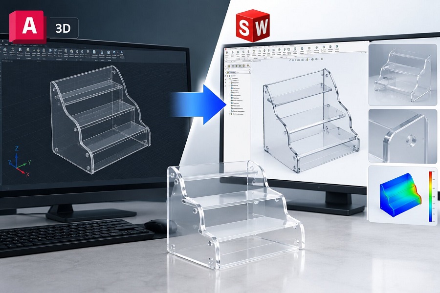
Enginerio recommended moving the modeling workflow from AutoCAD 3D to SolidWorks.
The objective was not simply to change the software.
The objective was to establish a more controlled, parametric, assembly-driven design process.
The proposed workflow was:
Design Input → SolidWorks Part Modeling → Parametric Features → Assembly → Interference/Design Check → Drawing → QC → Production
Why SolidWorks Was a Better Fit
SolidWorks provided several advantages for this type of product.
1. Parametric Part Modeling
Instead of relying heavily on coordinates and UCS positioning, components could be created using controlled sketches, dimensions, planes, and features.
For example, angled geometry could be created using:
- Reference planes
- Fully/partially defined sketches
- Extrude features
- Extruded cuts
- Construction geometry
- Defined dimensions
This made the design intent easier to understand and modify.
2. Assembly-Based Design
The acrylic stand consisted of multiple individual components.
Using SolidWorks assemblies allowed the team to bring the parts together and evaluate how they interacted.
This provided a significant advantage over treating each component as an independent 3D object.
The team could verify:
- Component positioning
- Overall dimensions
- Alignment
- Clearances
- Fit between components
- Assembly relationships
- Potential interference
3. Accurate Angled Features
One of the major challenges in the original AutoCAD process was creating features at the required angles using UCS and extrusion methods.
In SolidWorks, these features could be controlled using reference geometry and parametric features.
This reduced dependence on manually managing coordinate systems.
4. Design Intent Was Preserved
One of the biggest improvements was the ability to maintain relationships between dimensions and features.
If a key dimension or angle changed, associated features could update accordingly instead of requiring multiple manual corrections.
This significantly reduced the possibility of creating disconnected or inconsistent geometry.
Quality Control Improvement
During the initial stage, additional QC resources had to be introduced because of the number of errors and revisions generated during modeling.
The QC process became relatively time-consuming because engineers were repeatedly correcting:
- Angles
- Dimensions
- UCS-related geometry
- Extrusion locations
- Component positioning
- Drawing details
This created a cycle of:
Engineering → QC → Correction → QC → Correction → Release
After transitioning to SolidWorks, the process became more controlled.
The team could perform checks directly within the part and assembly environment before the drawing reached the final QC stage.
The revised workflow became:
Engineering → Self-Check → Assembly Validation → QC → Production
This reduced the amount of rework reaching the QC stage.
Production Impact
For an acrylic cosmetic display stand, dimensional accuracy is critical because the components ultimately need to be manufactured and assembled physically.
A CAD error can result in:
Incorrect CAD Geometry → Incorrect Drawing → Incorrect Fabrication → Assembly Issue → Rejection/Rework
By using a parametric SolidWorks model and assembly-based validation, the team was able to identify potential issues earlier in the design process.
The objective was therefore not only to create a visually correct 3D model, but to create a production-ready digital representation of the product.
Before vs. After
| Area | AutoCAD 3D Workflow | SolidWorks Workflow |
| 3D Part Modeling | Coordinate/UCS dependent | Parametric modeling |
| Angled Features | Manual UCS/extrusion workflow | Reference geometry/features |
| Assembly Validation | More manual | Dedicated assembly environment |
| Design Changes | More manual corrections | Parametric updates |
| Design Intent | Difficult to maintain | Easier to maintain |
| Error Detection | Often during QC | Earlier during modeling/assembly |
| QC Dependency | High | Reduced |
| Rework | Higher | Lower |
| Production Confidence | Dependent on checking | Improved through validation |
| Team Scalability | Dependent on individual expertise | More standardized workflow |
Engineering Lessons Learned
One of the most important lessons from this project was that software selection can directly affect engineering quality and productivity.
The original AutoCAD process was not necessarily wrong. It was the client’s established methodology and could be successfully executed by experienced users.
However, when the project was scaled across a team with different levels of AutoCAD 3D experience, the process became more difficult to control.
This highlighted an important engineering principle:
A good engineering process should not depend entirely on the individual engineer’s experience. The CAD methodology itself should help prevent errors.
By introducing SolidWorks, we were able to move toward a more standardized and controlled modeling approach.
Enginerio’s Approach
Rather than simply accepting the existing workflow and continuously adding QC resources, Enginerio analyzed the recurring errors and identified the underlying process limitation.
Our approach was:
1. Understand the Client’s Existing Process
We first learned the client’s AutoCAD 3D methodology and production requirements.
2. Identify Recurring Errors
We tracked issues related to UCS, angles, dimensions, and component relationships.
3. Analyze the Root C
We determined that the process was highly dependent on manual modeling practices and individual AutoCAD 3D expertise.
4. Recommend a Better CAD Methodology
We proposed SolidWorks part and assembly modeling as a more controlled alternative.
5. Implement Parametric Modeling
Parts were created using sketches, dimensions, reference geometry, extrusions, and cuts.
6. Validate Through Assemblies
Individual components were brought together to verify fit, positioning, and overall design.
7. Strengthen QC
QC remained an important part of the process, but the focus shifted from finding basic modeling errors to validating the final engineering output.
Business Benefits
The transition provided several important benefits:
- Improved modeling consistency.
- Better control of angled features.
- Reduced dependency on UCS knowledge.
- Improved assembly validation.
- Earlier identification of design issues.
- Reduced engineering rework.
- Reduced repetitive QC corrections.
- Improved production readiness.
- Better scalability across the engineering team.
- More structured CAD data for future design modifications.
Most importantly, the project demonstrated that quality should be built into the design process rather than added only at the inspection stage.
Conclusion
The acrylic cosmetic display stand project began with an established AutoCAD 2D/3D workflow that had been successfully used by the client.
However, as the project was transferred to a larger engineering team, challenges with AutoCAD 3D modeling, UCS management, angled extrusions, and design consistency resulted in increased rework and QC effort.
Enginerio identified that continuously increasing QC was not the most effective long-term solution.
Instead, we recommended transitioning the modeling methodology to SolidWorks, using parametric part modeling and assembly-based design validation.
This created a more structured engineering process in which design intent could be maintained, components could be validated together, and potential production issues could be identified earlier.
This experience reinforced Enginerio’s philosophy:
Design it right. Validate it early. Build quality into the process.
The project also demonstrated how the right combination of CAD methodology, engineering expertise, assembly validation, and QC can significantly improve the reliability and production readiness of a design.